- 您现在的位置:买卖IC网 > Sheet目录19076 > 91319-2 (TE Connectivity)10 ROW RECPT SEAT TOOL
!
i
Seating Tools 91318-- [ ], 91319-- [ ], and 91320-- [ ]
3.2. Application Tooling
Power for the seating tool must be provided by a
machine capable of supplying a downward force of
89 Newtons (N) [20 lb] per contact. Manual Electric
Servo Press (MEP 6T) 2--1399500--5 and Bench Top
Electric Servo Presses (BMEP 3T) 1--1399400--5 and
(BMEP 5T) 2--1399401--4 are available for this
seating tool. For information on the presses, visit the
press--fit assembly equipment website at
http://tooling.tycoelectronics.com/pressfit.asp .
4. SEATING
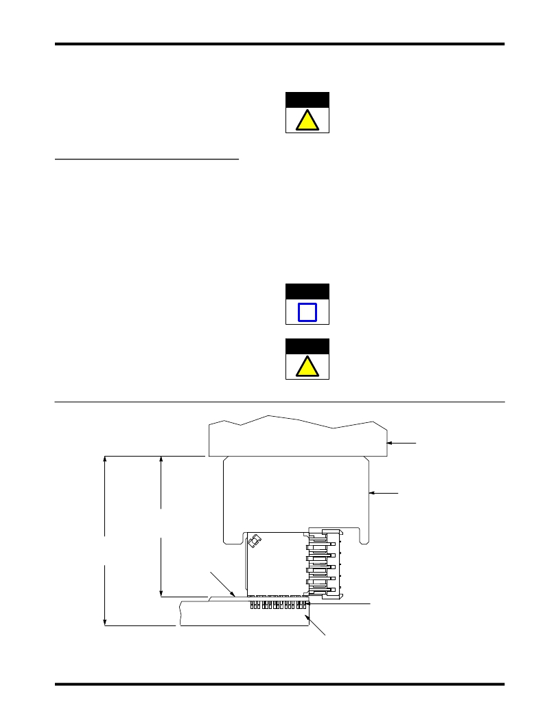
1. Set seating height to the dimension shown in
Figure 2 (applicator shut height will equal the
seating height PLUS the combined thicknesses of
the pc board, and pc board support fixture).
2. Position the connector onto the pc board so that
the contacts are properly aligned with the holes in
the pc board and the holes or slots in the pc board
support fixture. See Figure 2.
3. Sit the connector onto the pc board until the tips
of the contacts are resting securely on, but have
not fully entered, the holes in the pc board.
408-- 4571
meets the seating tool. Verify the alignment of the
pc board support fixture, pc board, connector, and
seating tool.
CAUTION Damage to the pc board, seating tool, or
connector may occur if seating height is
improperly set, if the pc board is not properly
positioned with the seating tool, or if the seating
tool is not properly seated on the connector
before cycling the applicator ram.
6. Cycle the applicator ram according to
instructions for the application tooling.
7. Remove the pc board with the seated connector,
and check the connector for proper seating
according to the following:
a. the widest section of each contact is inside its
intended pc board hole
b. the connector is seated on the pc board with
the seating height given in Figure 2.
NOTE For detailed inspection requirements of the
seated connector assembly, refer to Application
Specification 114--13020.
4. Position the seating tool onto the connector with
the slanted surface oriented as shown in Figure 2.
5. Center the seating tool and connector under the
applicator ram, and slowly lower the ram until it just
CAUTION
!
A damage connector should not be used. If a
damaged connector is evident, it should be
removed from the pc board and replaced with a
new one.
View After Seating
Applicator Ram
(Fully Down)
Applicator
Shut Height
(Ram Down)
Seating Height
(Connector Seated)
38.1 [1.50]
PC Board
Figure 2
Seating Tool Centered
Under Applicator Ram and
Bottomed on Connector
Contacts in PC Board Holes
and Holes or Grooves in
PC Board Support Fixture
PC Board Support Fixture
(Customer Supplied)
2 of 3
Tyco Electronics Corporation
Rev A
发布紧急采购,3分钟左右您将得到回复。
相关PDF资料
P51-200-G-O-P-5V-000-000
SENSOR 200PSI 7/16-20UNF 2B 1-5V
P51-100-G-O-P-5V-000-000
SENSOR 100PSI 7/16-20UNF 2B 1-5V
ASA-40.000MHZ-L-T
OSC 40.000 MHZ 3.3V SMD
553-0322
LED 3MM 5V GREEN
78C06RAT
SWITCH DIP RAISE SLIDE 6POS
P51-750-S-Y-P-5V-000-000
SENSOR 750PSIS 7/16 5V
P51-75-G-O-P-5V-000-000
SENSOR 75PSI 7/16-20UNF 2B 1-5V
P51-50-G-O-P-5V-000-000
SENSOR 50PSI 7/16-20UNF 2B 1-5V
相关代理商/技术参数
91319-3
功能描述:手工工具 10R RECPT SEAT TOOL
RoHS:否 制造商:Molex 产品:Extraction Tools 类型: 描述/功能:Extraction tool
913-194
制造商:SPC Multicomp 功能描述:CAPACITOR 47UF 63V
913-195
功能描述:支架与垫片 Plastic Spcr .195 in Nylon White RoHS:否 制造商:Schurter 类型:Transipillar Spacers 长度:16 m 螺纹大小:M4 外径:10 mm 材料:Nylon with Steel 电镀:Zinc
9131-9573-003
制造商:AEP 功能描述:
9131B
功能描述:DC POWER SUPPLY 30V/6A 5V/3A 制造商:b&k precision 系列:9130B 零件状态:有效 类型:工作台(AC 至 DC) 电压 - 电源:110VAC,220VAC 电压 - 输出:0 ~ 30VDC,0 ~ 30VDC,0 ~ 5VDC 电流 - 输出:0 ~ 6A,0 ~ 6A,0 ~ 3A 显示类型:VFD 字符数:- 输出数:3 大小/尺寸:17.520" 长 x 8.445" 宽 x 3.472" 高(445.00mm x 214.50mm x 88.20mm) 特性:存储器,可编程,LAN,RS232,和 USB 接口 功率(W):375W 精度 - 电压表;安培计:0.03% + 10mV;0.1% + 5mA 电压调节 - 线路:0.01% + 3mV 电压调节 - 负载:0.01% + 3mV 电流调节 - 线路:0.1% + 3mA 电流调节 - 负载:0.1% + 3mA 纹波:1mV rms 重量:33 磅(15kg) 标准包装:1
913-1MM
功能描述:支架与垫片 Plastic Spcr 1mm Nylon White RoHS:否 制造商:Schurter 类型:Transipillar Spacers 长度:16 m 螺纹大小:M4 外径:10 mm 材料:Nylon with Steel 电镀:Zinc
9131RB-K
制造商:Bud Industries Inc 功能描述:A STEEL METAL HINGE, MALE SHORT LEFT HANDED HINGE, POWDER COATED IN ROYAL BLUE (
9132
制造商:Abbatron/HH Smith 功能描述:Standoff; Hex; Brass; 2-56 Thread; 3/16" OD; 1/4" Length; Full Thread 制造商:GC Electronics 功能描述:FINE LINE SOLDER 12FT 制造商:Fluke Electronics 功能描述:LOW-MELT SOLDER 制造商:GC Electronics 功能描述:Low-Melt Solder
